
Designing the Shaft Interface for a 5 mm Motor Shaft
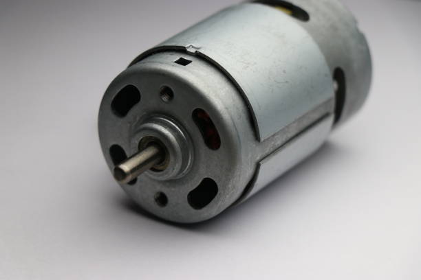
Engineers spend hours on windings and minutes on the shaft. Then the prototype arrives and the pinion slips, the pulley wobbles or the bearing starts to whine. The shaft is where the motor’s output meets your mechanism, so it deserves more care than it usually gets.
What the Published Data Tells You
MGLORY’s RS775 guide lists a 5 mm shaft made of stainless steel, supported by a ball bearing, in a motor housing made of SECD steel. The body is about 42.2 mm in diameter and 66.5 mm long. Those are the facts to start from.
The guide also warns that motors called RS775 can use different shafts, mounting details or end caps, and that shaft extension should be confirmed on the outline drawing. Treat the 5 mm figure as a starting point, not the whole interface.
Choose the Connection Method Early
A pinion, pulley or coupling must grip the shaft without slipping and without damaging it. Decide how that will happen before you finalise the mechanism. Will the part be pressed on, clamped, keyed or held another way? Each method has its own requirements for shaft length and surface.
Confirm the shaft engagement length on the drawing. A hub that only just reaches the shaft has little margin for tolerance.
Respect Side Loads
A ball bearing supports the shaft well, but it does not remove the need to control belt tension or gear mesh. The guide is clear that the product structure or a gearbox should carry excessive side loads rather than passing them to the motor shaft.
Ask the supplier for the permitted radial and axial shaft loads for your winding and configuration. Then calculate the loads your design creates, with belt tension or gear forces included, and compare them.
Account for Startup Torque
Shafts see their highest torque during startup and during jams. A coupling that holds comfortably at running torque can slip at startup. Mounting must resist startup torque without flexing, so check both the shaft connection and the bracket.
Stall torque is a short-duration limit, but your mechanism could still meet it if something jams. Design the interface to survive that moment or protect it with a clutch or current limit.
Keep Everything Aligned
Misalignment creates vibration, noise and uneven wear. Check the alignment between the motor shaft and the driven part when the motor is mounted, not just in CAD. Tolerances stack, and a small offset at the bracket becomes a larger one at the load.
Confirm the rs775 dc motor datasheet and drawing agree on shaft details before releasing tooling. Mismatched documents are a common source of late changes.
Protect the Shaft Area
Think about what reaches the shaft end of the motor. Dust, moisture, fibres and metal particles are worth a line in your design review. Contamination near the bearing can shorten its life, and fibres can wrap around exposed rotating parts.
Use the Basic Dimensions Wisely
The published 775 motor dimensions give you the shaft diameter, body diameter and length for early layout. Use them to place the motor and size the first housing, then update the model as soon as the outline drawing arrives.
Never freeze a design on nominal figures.
Inspect After Testing
After a validation run, remove the coupling and examine the shaft. Look for polishing, scoring or marks that suggest slipping. Listen for bearing noise and check for play. These signs appear in testing long before a customer would notice them.
Record what you find. If the same mark appears on every sample, the interface needs redesign, not the motor.
Direct Drive, Gears or Belts?
The drive method changes the load on the shaft. A direct coupling usually asks the least of the bearing, provided the alignment is good. A gear mesh creates radial force at the pinion. A belt creates a steady sideways pull that depends on how tightly it is tensioned.
The guide’s advice fits all three: let the product structure or a gearbox carry large side loads. A gearbox with its own bearings can take the burden off the motor shaft, which is one reason to consider it early.
Questions to Put to Your Supplier
Send a short list before you commit. Which shaft length applies to my winding? What radial and axial loads are permitted? Are flats or other features available if my coupling needs them? Can the shaft be customised?
MGLORY says it can evaluate custom shaft requirements, so ask early rather than late. A written answer with a drawing reference is worth far more than a verbal assurance.
Conclusion
A reliable shaft interface comes from clear documents, a chosen connection method, controlled side loads, startup torque margin and careful alignment. Spend the time early, inspect after testing and keep the drawing in charge. The motor will reward you with steady service.